Ball Grid Array Inspection Techniques
Ball Grid Array Inspection Techniques
As consumer and commercial electronics have evolved, products have become increasingly smaller and lightweight while providing high performance. Ball grid array and surface-mount technology used on printed circuit boards have become increasingly essential, particularly for high-density and quick assembly requirements.
BGA inspections can pose several challenges and require specialized knowledge and tools. It's crucial to understand the complexities of BGA inspection methods such as visual examination, X-ray inspection, infrared thermography and acoustic microscopy.
You can improve quality control and avoid defects by mastering the various inspection techniques and knowing when to conduct them.
What Is a Ball Grid Array Inspection?
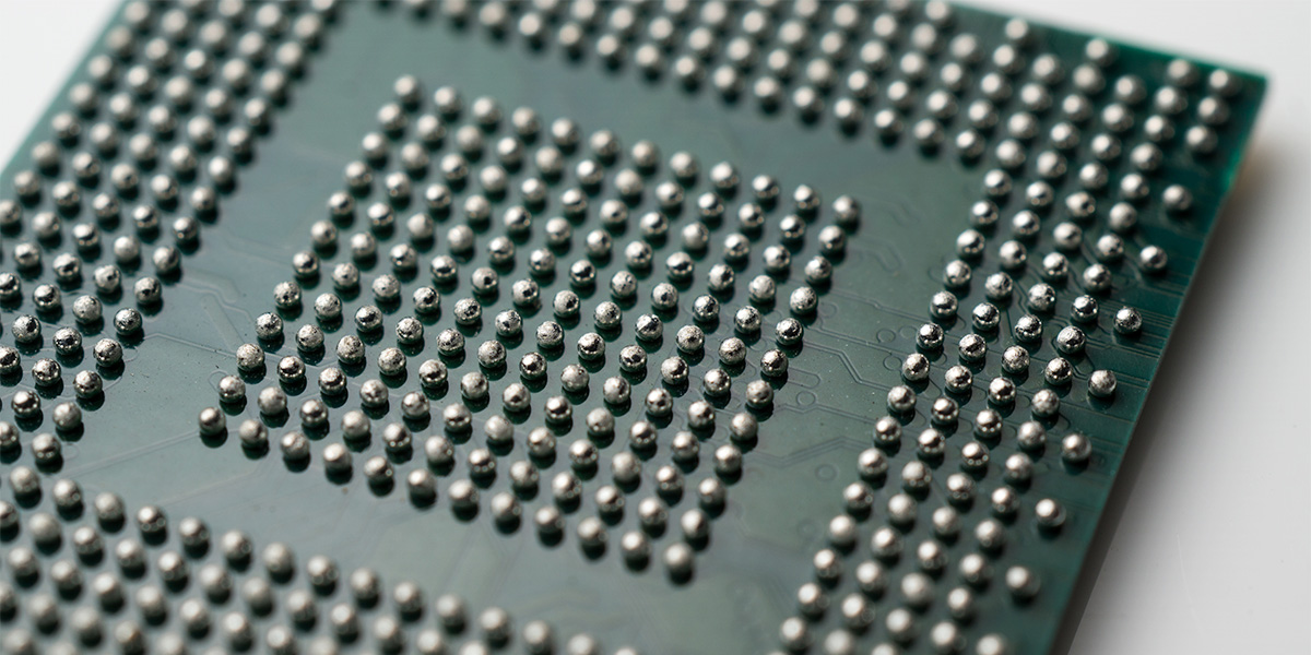
A BGA inspection is a meticulous process where you check the integrity of electronic assemblies. Modern BGAs consist of integrated circuits mounted on PCBs using an array of solder balls beneath the component. The intricate design ultimately enhances space efficiency, but presents challenges, such as technicians needing to ensure the connections are effective.
The inspection involves scrutinizing the solder joints that connect the BGA components to the PCB. BGAs are subject to several stress factors, such as inadequate soldering, bridging, voiding and component misalignment.
Conducting inspections serves a dual purpose. Firstly, it allows you to verify the solder joints' structural integrity and ensures they can withstand mechanical stress and thermal cycling. Secondly, it assesses the BGAs' electrical functionality for reliable signal transmission.
Timely inspections help detect defects, prevent malfunctions and enhance electronic systems' overall reliability. BGAs are vital in electronic devices, so inspections let engineers, manufacturers and technicians assess optimal product performance and longevity.
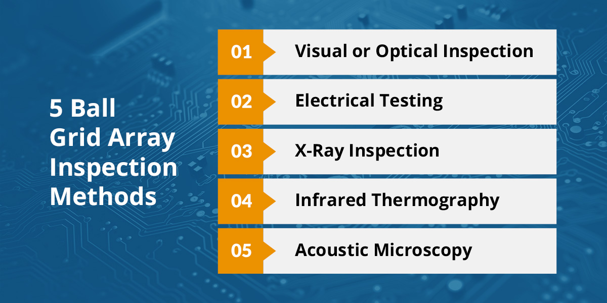
5 Ball Grid Array Inspection Methods
Ball grid array inspection techniques include the following. Sometimes, you may need to combine approaches to thoroughly evaluate BGA components' performance.
1. Visual or Optical Inspection
Visual inspection is the straightforward process of looking for defects. Technicians often use magnification tools to inspect the solder joints and components for possible irregularities, such as solder ball misalignment or bridging. However, optical methods have advanced with time.
This method provides a quick and convenient initial assessment of the BGA components and can identify potential issues purely based on evident defects. This method is appropriate and effective at detecting uses like misalignment or insufficient solder application.
2. Electrical Testing
Electrical testing ensures BGA integrity by detecting performance defects in BGA connections. You would use specialized equipment such as a multimeter or flying probe tester to measure electrical parameters like resistance and continuity across the BGA components.
Conducting electrical testing ensures each solder joint functions as intended and confirms the absence of open circuits or irregular electrical behavior.
3. X-Ray Inspection
X-ray BGA inspection is a non-destructive method that offers beneficial insights into the components' internal structure and integrity. When using X-ray imaging, technicians can visualize the quality of solder joints and identify any defects such as insufficient solder, internal connection issues and voiding.
You would use X-ray inspection to help uncover defects that are invisible to the naked eye. It provides a far more detailed view of the internal solder joint quality and identifies hidden issues you otherwise wouldn't notice, which could compromise the BGA's reliability.
4. Infrared Thermography
Infrared thermography involves capturing the heat signature of BGA components, which you would analyze to identify anomalies. You can detect temperature variations using an infrared camera, which helps reveal potential issues such as poor thermal distribution, overheating or irregularities in solder joints.
Infrared thermography is a valuable method for assessing BGA components' thermal performance. It quickly identifies temperature irregularities and can prevent overheating to ensure the longevity and reliability of electronic assemblies.
5. Acoustic Microscopy
Acoustic microscopy, also known as acoustic micro-imaging, has applications similar to X-ray inspection but uses different technology. Instead of X-rays, it uses high-frequency soundwaves to create images of the internal structure of the BGAs. It works by transmitting the soundwaves through the BGA component, and the variations in acoustic impedance provide detailed imaging that reveals any defects such as voiding or delamination.
Like X-ray inspection, acoustic microscopy is beneficial for identifying defects within the BGA structure that you cannot see with a simple visual inspection. Ultimately, it offers a far more comprehensive assessment than some other inspections.
Common BGA Defects and Causes
Solder ball grid array components have intricate designs and compact footprints and are pivotal to modern electronics. However, they are not immune to defects. Let's examine five of the most common issues you are likely to encounter, with an explanation of possible causes and effects.
- Solder ball defects: These usually result from irregular solder application during manufacturing. Differently sized solder balls lead to uneven stress distribution during temperature fluctuation, ultimately compromising the solder joint's structural integrity and connectivity.
- Bridging: This problem occurs when excess solder connects adjacent balls. These unintended connections can short-circuit neighboring solder balls, disrupting the intended electrical pathways and likely causing malfunction in the electronic circuit.
- Voiding: Voids are empty spaces within the solder joint due to trapped air or inadequate flux. This challenge can undermine the joints' mechanical strength and electrical conductivity.
- Lifted or tilted components: This obstacle has several causes, ranging from uneven heating to insufficient solder paste to misalignment during assembly. Lifting or tilting will likely adversely impact electrical connections and compromise mechanical stability.
- Open circuits: This issue results from incomplete solder joints or solder fatigue and occurs when there is an interrupted connection in the solder joint. The problem disrupts electrical signals and impacts the BGA component's function.
Contact Precision PCB Services for BGA Training and Solutions
Precision PCB Services offers BGA rework stations to help you set up your in-house end-to-end BGA rework process. We also teach classes for those with the necessary equipment who require advanced BGA training and other courses. These include BGA reballing, BGA rework process implementation and BGA rework station operation training. Let us help you avoid common BGA rework mistakes familiar to those who have worked on these unique components.
Alternatively, you can contact us today to discuss our service offerings, including all aspects of BGA reworking.


